Introduction:
Not all motion systems are created equal, and the motor you choose can determine whether your project is a success or a failure. From 3D printers to industrial robots, choosing between stepper and servo motors directly impacts speed, accuracy, and cost. Yet, many makers and engineers are unsure which one truly fits their needs.
Are you trying to decide between simple open-loop control and adaptive precision with feedback? Or wondering if the extra cost of a servo system is worth it for your CNC build or automation setup?
Both motor types have their place, but choosing the wrong one can lead to missed steps, overheating, or a wasted budget. The good news? You don’t need to guess.
In this guide, we’ll explain how stepper and servo motors work, compare their respective advantages and disadvantages, and discuss real-world applications to demonstrate their optimal performance. Whether you’re building your first motion system or refining an existing machine, you’ll leave with the knowledge and confidence to make the right decision for your project.
Understanding the Fundamentals of Motion Control
In the previous section, we introduced the broader decision-making challenge of choosing between stepper and servo motors. We emphasized how this choice impacts precision, performance, and system cost. To make an informed decision, it’s essential to first understand the fundamentals of motion control: what it is, how it works, and where motors fit within these systems.
What Is Motion Control, and Where Do Motors Fit?
Definition of Motion Control Systems and Core Components
Motion control is a branch of automation that focuses on precisely controlling the movement of mechanical systems. It’s the technology behind everything from CNC machines and 3D printers to robotic arms and automated inspection stations. At its core, a motion control system translates digital commands into mechanical movement with sub-millimeter precision.
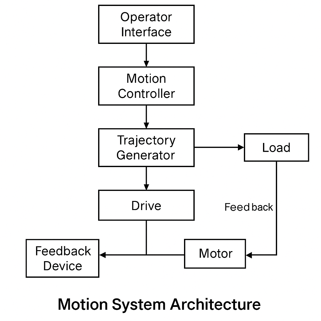
Figure 4 illustrates a typical motion system architecture. Commands from the user interface are interpreted by the controller and translated into drive signals. Feedback from sensors helps maintain precise motor control under dynamic load conditions.
A standard motion control setup includes:
- A controller that interprets motion commands (e.g., G-code or PLC logic) and sends signals to drives or amplifiers.
- Drive (or driver): Converts control signals into an electrical current suitable for motor operation.
- Motor: Converts electrical energy into mechanical movement (rotation or linear).
- In servo systems, a feedback device (e.g., an encoder or resolver) reports position and velocity back to the controller for closed-loop adjustments.
- The mechanical load is the machine axis, tool, or part being moved.
The motor is a critical element in this chain. It directly influences how quickly, accurately, and reliably a system can execute motion commands.
The Role of Motors in Precision Automation and Positioning Systems
Motors serve as the actuators in a motion system. They physically move components along a specified path with high precision and repeatability. In applications such as CNC milling, laser cutting, pick-and-place operations, and automated camera positioning, even minor inaccuracies in motion can result in poor outcomes, mechanical wear, or safety concerns.
Key motor requirements in such systems include:
- Precision: The ability to move to exact positions without overshooting or experiencing backlash.
- Torque: Sufficient rotational force to move a mechanical load without stalling.
- Responsiveness: Fast acceleration and deceleration for dynamic tasks.
- Repeatability: The ability to return to the same position repeatedly without drift.
The method by which the motor achieves these goals—open-loop control, as in stepper motors, or closed-loop feedback, as in servo systems—significantly affects performance, cost, and system complexity.
The two main players are: Stepper and servo.
Overview of Motor Categories Used in Hobbyist and Industrial Platforms
In modern motion control, stepper and servo motors dominate most applications. Each type of motor has distinct strengths and limitations depending on the task.
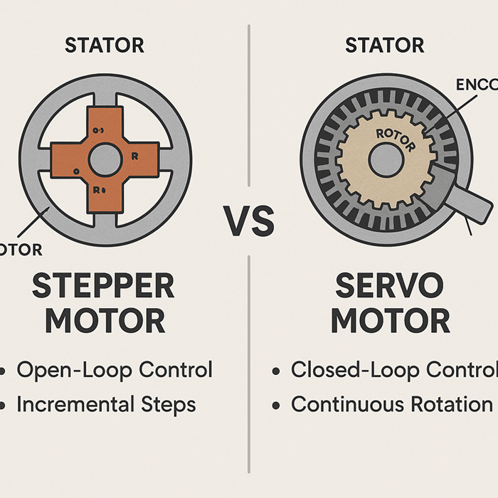
Figure 2 shows a comparison of the internal structure and control logic of stepper motors and servo motors. Stepper motors use open-loop control and move in discrete steps. Servo motors, on the other hand, rely on closed-loop feedback with encoders for continuous precision.
Stepper motors move in discrete steps and typically operate in open-loop mode, meaning they don’t rely on position feedback to determine their location. They are valued for their simplicity, low cost, and ease of integration, especially in lower-load or lower-speed applications.
Servo motors, in contrast, are part of a closed-loop system. They use feedback sensors to continuously monitor position, speed, and torque, allowing them to adjust in real time. Servo motors excel in demanding, high-speed, or high-precision applications, but they are more expensive and complex to integrate.
Other motor types exist, such as brushed DC, BLDC (brushless DC), and linear actuators, but they are usually employed in specialized or embedded systems. For most makers, machine builders, and industrial automation designers, the real decision boils down to stepper versus servo motors.
Where Stepper and Servo Motors Are Typically Applied
Stepper motors are widely found in:
- Entry- to mid-level 3D printers
- Desktop and hobby-grade CNC routers
- Laser engravers and plotters
- Automation jigs with repetitive, low-speed motion
They are also ideal for cost-sensitive DIY robotics and mechatronics projects.
These are ideal for:
- Precise control is needed without expensive feedback systems
- Loads are predictable and low-to-moderate in inertia
Cost and simplicity are prioritized over high-end performance.
Servo motors are commonly used in:
- Industrial CNC machines (e.g., metal milling centers)
- Robotic arms and articulated manipulators
- Automated production lines requiring high throughput
- Camera gimbals
- UAVs
- Real-time stabilization systems
These systems are preferred when:
- Continuous feedback and dynamic motion adaptation are essential
- High torque is required across a broad RPM range
- Energy efficiency and long-term reliability justify the higher upfront cost
How Stepper Motors Work
In the previous section, we explored the fundamentals of motion control systems and highlighted how motors act as core actuators that convert electrical signals into precise mechanical motion. We also introduced the two most common motor types, stepper and servo motors, and outlined their respective areas of excellence. Now, we’ll take a closer look at stepper motors: how they function, how they’re controlled, and why they remain a popular choice in many precision motion applications.
Step-by-Step Operation and Control
How Stepper Motors Move Incrementally
A stepper motor moves in fixed, incremental steps. Each full rotation is divided into a specific number of discrete steps—commonly 200 steps per revolution (1.8° per step), according to the Stepmotech NEMA 23 datasheet—which enables precise positioning without the need for feedback. Internally, the motor contains multiple coils that are energized in a predefined sequence. As each coil activates, it creates a magnetic field that aligns the rotor to a new position.
The controlled magnetic attraction between the stator and rotor enables fine positional control, which is ideal for applications requiring repeatable linear or rotary movement.
Open-loop Control Systems Do Not Require Feedback
Stepper motors are typically operated in an open-loop system, meaning the controller sends movement commands without receiving position feedback. The assumption is that the motor will move exactly as instructed. As long as the motor isn’t overloaded or commanded beyond its torque capacity, it will reach the expected position.
In systems using GRBL 1.1f or later, stepper movement is controlled via step/dir pulses with configurable acceleration and jerk limits. These values are set through firmware parameters, such as $120 for the X-axis, $121 for the Y-axis, and $122 for the Z-axis. These settings directly influence the stepper’s ability to reliably complete moves without losing steps during rapid direction changes.
[A technical schematic diagram in black and white.]
Basic Stepper Motor Control System Architecture
The controller sends step/direction signals to the stepper driver, which regulates power delivery to the motor.
This open-loop architecture offers several advantages:
- Simplified system design: No need for encoders or feedback loops.
- Lower cost: fewer components and simpler electronics
- Predictable behavior: Movement is deterministic based on step count.
However, open-loop systems lack error correction. If the motor skips steps due to overload or acceleration limits, the system won’t detect or compensate for the error. This is one of the trade-offs discussed later in this section.
Types of Stepper Motors and Driver Systems
Permanent Magnet vs. Hybrid vs. Variable Reluctance Types
Stepper motors fall into three primary categories, each with distinct construction and performance traits.
Permanent Magnet (PM) Stepper Motors:
They use a permanent magnet rotor. They typically have low torque and low resolution and are often used in small, simple devices like clocks or toys.
Variable Reluctance (VR) Stepper Motors:
They feature a soft iron rotor with no magnetism. They rely on rotor alignment with magnetic fields. They are rarely used today due to their poor torque characteristics and limited resolution.
Hybrid Stepper Motors:
They combine the strengths of permanent magnet (PM) and VR designs. They are the most common type used in CNC machines, 3D printers, and automated systems due to their high torque density, fine step resolution, and smooth motion characteristics.
For most motion control applications, hybrid stepper motors offer the best balance of performance and cost.
Microstepping, Full-Step, and Half-Step Drive Modes
The way a driver energizes the motor coils affects how smoothly and accurately the motor moves.
Full-Step Mode:
Energizes two coils at once, producing maximum torque per step, but with coarse motion.
Half-Step Mode:
Alternates between energizing one or two coils. This effectively doubles the step resolution, resulting in smoother motion at the expense of slightly reduced torque in single-coil steps.
Microstepping:
It divides each step into multiple fractional steps by varying the current levels sinusoidally across the coils. Common configurations include eight, 16, or 256 microsteps per full step.
Microstepping improves smoothness and positional resolution; however, torque per microstep is reduced, and actual positional accuracy depends on system load and friction.
Common driver chips, such as the TMC2209 (used in UART mode), support up to 256 microsteps per full step. These chips also integrate stealthChop and spreadCycle modes for motion smoothing. These features are typically accessed via firmware such as Marlin 2.1.x or Klipper, along with the corresponding driver configuration in Configuration_adv.h.
To achieve optimal microstepping performance, correctly configure the driver’s current decay mode (e.g., fast, slow, or mixed decay) and the motion controller’s pulse timing. For instance, configuring stealthChop vs. spreadCycle modes on a TMC2209 driver affects acoustic noise and step integrity at low RPMs. Additionally, tuning the acceleration curve in GRBL (e.g., using the $120–$122 settings) directly impacts stepper reliability at high feed rates.
Selecting the appropriate stepping mode requires balancing torque, smoothness, and resolution and is often dependent on the specific application’s requirements.
Pros of Stepper Motors in Real-World Applications
Stepper motors are prized for their mechanical simplicity, predictable movement, and low system cost. Since they don’t require position feedback or complex control algorithms, they’re easy to integrate into low- to mid-level motion platforms.
Key Advantages Include:
- High precision at low speeds without encoders
- Excellent holding torque, ideal for static positioning
- Repeatable performance in fixed-path or repetitive tasks
They are low maintenance, with fewer parts subject to wear compared to brushed motors.
These characteristics make stepper motors a reliable solution for predictable motion within budget constraints.
For instance, in our tests, we used a NEMA 23 stepper motor and a DM542 driver on a LowRider v3 CNC machine and achieved reliable wood routing at a feed rate of up to 1000 mm/min without skipped steps or overheating. The predictable path control made open-loop control sufficient for consistent panel cuts.
Ideal Scenarios
- 3D printers: X, Y, Z, and extruder axes
- Laser cutters and engravers, which require fast, repeatable linear motion
- DIY CNC machines, including routers and plasma cutters
- Camera sliders, pan/tilt mounts, and other motion rigs
- Laboratory instruments require precision motion without high dynamic loads
These applications have well-characterized loads and minimal need for real-time feedback, making open-loop stepper systems practical and economical.
In a popular open-source build log on the r/DIYElectronics subreddit, users documented how NEMA 23 steppers running on TMC2209 drivers achieved 50 μm precision for laser engraving without missed steps using only open-loop control (October 2022 thread).
Common Limitations and Performance Challenges
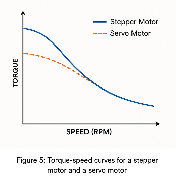
Torque Drop-Off at High Speed
One inherent drawback of stepper motors is their nonlinear torque curve. As rotational speed increases, available torque decreases sharply. This is due to inductance in the coils, which impedes rapid current changes at higher frequencies.
As a result:
- Stepper motors are best suited for low- to moderate-speed applications.
- High-speed use often requires oversized motors or higher-voltage drivers to compensate for torque loss.
Missed Steps and Resonance Under Load
Without feedback, stepper motors can lose synchronization if they are asked to move faster or push harder than their torque allows. This results in missed steps, leading to cumulative position errors.
Other common issues include:
- Resonance: Natural frequencies in mechanical systems can amplify vibration and reduce smooth motion.
- Overload sensitivity: Sudden changes in load can cause the motor to stall.
Some of these issues can be mitigated by:
- Proper acceleration tuning
- Adding dampers
- Using closed-loop stepper drivers with encoder feedback
Heat Generation During Hold Position
Stepper motors consume power even when idle if holding torque is required. Holding current generates heat in the windings, which can lead to reduced motor lifespan.
- Reduced motor lifespan
- Increased system cooling requirements
- Thermal drift in precision applications
Proper current limiting and thermal management, such as fans or heat sinks, are often required in systems that operate continuously.
How Servo Motors Work
In the previous section, we examined how stepper motors operate through incremental movements. We highlighted their affordability, simplicity, and suitability for low- to mid-speed applications. While stepper systems offer dependable performance in open-loop environments, they are inadequate for high-speed, high-precision, or dynamically changing loads. In such scenarios, real-time feedback and adaptive response are critical. This brings us to servo motors, which are designed to address these performance gaps through closed-loop control systems and precision feedback mechanisms.
Closed-Loop Feedback and Adaptive Control
Real-Time Feedback with Encoders or Resolvers
Servo motors operate as part of a closed-loop system. This means the controller continuously monitors the motor’s actual position and velocity via feedback devices, such as encoders or resolvers. These sensors provide real-time data that enables the system to adjust for any deviation from the desired motion trajectory.
For example:
- If a load changes mid-move or an external force causes slippage, the feedback signal detects the discrepancy.
- The controller then immediately adjusts the current, torque, or speed to restore accuracy.
This feedback loop enables exceptional motion control, especially for tasks requiring tight positional accuracy or the ability to handle unpredictable loads.
PID Control and Precision Adjustment
The heart of a servo system’s intelligence is usually a PID (proportional-integral-derivative) control loop. This algorithm processes feedback data to:
- Proportionally respond to position errors,
- Integrate past errors to eliminate steady-state offsets,
- Differentiate rate of change to anticipate future errors.
This results in:
- Smooth motion without overshoot or oscillation,
- Fast response to changes in command or load,
- High stability in both static and dynamic conditions.
While powerful, PID tuning introduces complexity. Controllers must be precisely configured for the motor, load, and application dynamics to achieve optimal results. Improper tuning can lead to sluggish behavior, overshoot, or instability.
Types of Servo Systems and Components
AC vs. DC Servo Motors
Servo motors are available in two primary variants, each suited to different environments.
DC servo motors:
Operate at lower voltages (12V–48V) and are often found in compact or mobile systems, such as robotics, pan-tilt cameras, and small-scale automation. DC servos are typically easier to integrate and less expensive, but they may offer limited torque and durability in heavy-duty cycles.
AC servo motors:
Designed for industrial use and often operating at 220V or higher. These motors provide:
- Higher torque-to-inertia ratios
- Greater speed ranges
- Better thermal performance
AC servos are widely used in high-throughput systems, such as industrial computer numerical control (CNC) machines, robotic arms, and packaging machines. They have integrated drives, controllers, and feedback devices.
A Complete Servo System Includes:
- Servo drive (or amplifier): Receives motion commands from the controller and adjusts power delivery to the motor based on feedback signals.
- Motion controller: Executes path planning, PID logic, and synchronization. In some systems, the motion controller is embedded within the servo drive itself.
- Feedback device: Most commonly, it is an optical or magnetic encoder, though some systems use resolvers in rugged environments. These sensors track position, velocity, and, in some cases, torque.
Some modern servos are integrated packages that combine the motor, encoder, and drive into one unit. While this reduces wiring complexity and installation time, it may limit component-level customization.
Benefits of Servo Motors in High-Demand Applications
High Torque Across RPM Range
One of the most significant performance advantages of servo motors is their ability to maintain torque across a broad speed range. Unlike stepper motors, which experience torque drop-off at high speeds, servos can deliver consistent output at speeds of several thousand RPM.
This makes them ideal for:
- High-speed machining
- Rapid pick-and-place automation
- Continuous-duty applications requiring sustained dynamic motion
Servos also support torque control, enabling the system to apply a defined force, which is critical for tensioning, pressing, and force-sensitive operations.
They provide superior accuracy and stability under dynamic loads. Due to their feedback-based control, servo motors can adapt to changing conditions in real time.
For example:
- If a load increases unexpectedly, the drive increases the current to maintain speed.
- If the system vibrates or experiences backlash, the PID loop compensates to restore stability.
This makes servos particularly effective in:
- Robotics with articulated joints
- Multi-axis synchronized motion (e.g., delta robots and SCARA arms)
- Any scenario in which environmental forces may alter the system’s behavior during operation
A GitHub project by user @mechanicmind features an SCARA robotic arm that uses ClearPath servos with real-time torque correction to maintain ±0.02 mm accuracy during payload variation tests (GitHub, March 2023).
Technical Drawbacks and Cost Considerations
Higher Initial Cost and Setup Complexity
While servo motors offer clear performance benefits, they come with a higher price tag — not just for the motor itself, but also for the entire control architecture.
- Drives are more sophisticated and expensive than stepper drivers.
- Controllers must support feedback processing and advanced motion algorithms.
- Careful matching of motor, encoder, drive, and load characteristics is required for setup.
For small-scale or budget-sensitive projects, these costs may be prohibitive unless the application genuinely requires servo-level performance.
Tuning Requirements and System Integration Challenges
- Servo systems require precise tuning and calibration.
- PID values must be adjusted to match system inertia and damping.
- Encoder resolution must align with motion resolution requirements.
- Electrical noise and grounding must also be carefully managed to ensure accurate feedback.
Integrating components from multiple vendors may also introduce compatibility or configuration challenges. To simplify this process, many users opt for pre-matched servo kits from a single manufacturer, especially in industrial environments where reliability is critical.
Performance Comparison: Stepper vs. Servo Motor
In the previous section, we explored how servo motors use closed-loop feedback and adaptive control to achieve high precision, dynamic stability, and efficient high-speed performance, albeit at the cost of increased expense and complexity of integration. Now that we’ve outlined how stepper and servo motors function independently, this section will bring them together for a direct comparison across key technical dimensions. This comparison clarifies when one system offers a distinct performance or economic advantage over the other.
Torque, Speed, and Precision Characteristics
Comparative Overview of Motion Capabilities
When evaluating motor performance, three critical factors are torque, speed, and positioning precision.
While both motor types can drive precise motion systems, their operating principles result in very different behavior under load.
| Attribute | Stepper Motor | Servo Motor |
|---|---|---|
| Holding Torque | High (at standstill) | Variable; must be actively controlled. |
| Peak Torque | Limited and drops at high speeds | High and consistent across a wide range of speeds |
| Usable Speed Range | Best under 1000 RPM | Commonly 3,000–5,000 RPM |
| Positional Accuracy | Deterministic steps; may miss steps if overloaded | High; continuously corrected via feedback |
| Repeatability | Good (if not overloaded) | Excellent (adaptive to disturbances) |
| Torque-to-Weight Ratio | Moderate | Higher, especially in AC servos |
Key takeaway: Stepper motors perform best at low to moderate speeds with constant loads. Servo motors excel when high torque, wide speed ranges, or a dynamic response to variable conditions are required.
Control Systems and Complexity
Open-loop vs. Closed-loop Logic
Stepper motors operate in an open-loop configuration.
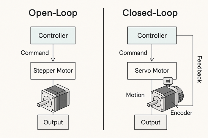
In open-loop systems, the controller sends commands to the stepper motor without feedback. It’s simple logic: move X steps and assume the position was reached. No feedback means no correction for missed steps or overload.
Servo motors use closed-loop logic. They monitor real-time position and velocity and actively correct deviations during operation.
While closed-loop control offers greater reliability and precision, it requires more from the hardware and software. Often, this includes a dedicated motion controller, encoder input handling, and tuning algorithms.
System Integration Requirements
Stepper systems:
- Generally plug-and-play
- Fewer signal wires (step/direction and enable)
- No feedback lines
- Minimal configuration for motion profiles and current settings
Servo systems:
- Signal wiring
- Feedback signal lines (encoder or resolver)
- Drive tuning (PID or auto-tune configuration)
- Software integration to match motor parameters, feedback scaling, and control loop timing
Stepper setups offer a lower barrier to entry for users with limited experience. However, servo systems provide far greater control and adaptability for applications that demand fine-tuned performance or real-time responsiveness.
Heat, Noise, and Power Efficiency
Passive vs. Active Cooling Needs
Stepper motors often draw constant current, even when stationary. Heat builds up during holding phases, and they may require external cooling, such as fans or heat sinks, in high-duty applications.
Servo motors modulate current based on load. They draw less current at idle and generate less waste heat. They are typically more efficient in continuous or variable-load applications.
Energy Draw and Efficiency Curves Under Load
Stepper Motors:
- Less efficient at higher speeds due to torque decay
- Poor energy usage when holding position under static load
Servo Motors:
- High efficiency across broad speed and load ranges
- Adaptive energy consumption (uses only what is needed at the moment)
Noise Levels
Stepper motors may produce audible “buzzing” or harmonic noise at certain speeds. Servo systems, especially modern digital drives, are significantly quieter.
Real-World Example Scenarios
Use Case 1: Desktop CNC Router vs. Industrial Router
Desktop CNC Router (Stepper): Uses NEMA 23 stepper motors with open-loop control for X/Y/Z motion. It has adequate torque at low speeds for plywood or soft materials. It is affordable, has minimal wiring, and has a simple setup.
Industrial CNC Router (Servo): It employs high-voltage AC servo motors for fast acceleration and sustained, high-speed cutting in hardwood or aluminum. Closed-loop feedback ensures zero missed steps and tighter tolerances under heavy spindle loads.
Use Case 2: 3D Printer Extruder vs. Robotic Arm Joint
3D Printer Extruder (Stepper): Fine microstepping provides accurate extrusion volume and repeatable nozzle positioning. The load is predictable, and cost and simplicity are key.
Robotic Arm Joint (Servo): The joint experiences variable forces during lift, pivot, and reach cycles. The servo motor with encoder feedback ensures dynamic correction, force control, and smooth motion throughout the arm’s range.
Use Case 3: Camera Pan-Tilt System vs. Pick-and-Place Machine
Camera Pan-Tilt (Stepper): Simple rotational movements, low inertia, and predictable motion paths. Quiet operation is less critical, and the stepper motor offers cost-effective control.
Pick-and-Place Machine (Servo): It requires precise timing and real-time adaptation to changing speeds, vacuum load variation, and multi-axis synchronization. The servo system ensures speed without sacrificing accuracy or stability.
A related discussion on the CNCZone forum details how missed steps in open-loop stepper systems can affect the repeatability of high-speed pick-and-place machines.
Cost and Maintenance Factors
In the previous section, we compared stepper and servo motors based on performance-critical factors such as torque, speed, control complexity, and energy efficiency. While technical capability is essential, cost and maintainability often have the final say in real-world decision-making, especially for small shops, educational projects, and scaled industrial deployments. In this section, we’ll break down the financial and operational factors that influence long-term motor system viability.
Initial Investment and Ongoing Costs
Motor and Driver/Controller Pricing Comparison
The initial cost difference between stepper and servo systems can be significant, especially when scaling across multiple axes. On average:
- Stepper motors and drivers (open-loop) are significantly less expensive. For instance, a NEMA 23 motor and digital driver combo may cost between $40 and $80 per axis.
According to the Leadshine DM542 datasheet, the driver supports a peak current of up to 4.2 A and microstepping of up to 256 levels. This makes it suitable for NEMA 23–based motion systems in CNC and 3D printing applications.
- Servo motors, even entry-level ones, are more costly due to their integrated feedback and higher precision requirements. A compact DC servo motor with a drive and an encoder can cost $150–$300 per axis, while industrial-grade AC servo systems often cost more than $500–$1,000 per axis.
Beyond the motor itself, servo systems require more sophisticated controllers with motion planning, PID tuning, and encoder handling capabilities. These features are usually optional or absent in most stepper-based systems.
Ancillary Costs (Power Supply, Encoder, Cable Management)
Power supplies:
Servo systems typically require higher-voltage, higher-current power supplies—often 48V, 60V, or even 220V—depending on the drive and motor rating. This increases the initial cost and the complexity of safe power distribution.
Encoders and feedback devices:
Servo motors rely on built-in or external encoders that must be matched, calibrated, and wired correctly. This adds hardware cost, as well as time and skill requirements during setup.
Cabling and Connectors:
Servo setups may require shielded twisted-pair cables, high-current connectors, and EMI protection. Compared to the simpler step/direction wiring used by most stepper drivers, this makes cable management more involved.
Overall, servo systems have a higher installation cost, which includes physical components and configuration time. For basic motion tasks, the added performance may not justify this overhead.
Reliability, Durability, and Maintenance
Moving Parts and Wear Factors
Both motor types are generally durable when correctly sized and operated within specifications, but they differ in failure modes and long-term behavior.
Stepper motors have fewer internal components—no brushes, no commutators, and typically no internal feedback sensors. This contributes to mechanical simplicity and high inherent reliability.
Servo motors, especially brushed DC types, may have wear-prone components, such as brushes or bearings, that degrade with use. However, brushless AC servos largely eliminate this concern and are designed for continuous duty cycles in industrial environments.
Maintenance Cycles and Serviceability
Stepper systems require almost no routine maintenance.
- No encoder alignment
- No software recalibration is necessary unless mechanical changes are made.
- Failures are often limited to overheating or driver failure, both of which can be easily diagnosed.
Servo systems, by contrast, benefit from periodic inspection and tuning.
- Encoder signal quality should be verified periodically.
- PID tuning may need to be adjusted as mechanical loads or application conditions evolve.
- Drive firmware updates, parameter backups, and system diagnostics are often part of standard maintenance workflows in industrial environments.
In applications where uptime is critical, the predictability and recoverability of servo system faults due to feedback data can simplify troubleshooting if the user has the necessary tools and expertise.
Long-Term Value vs. Upfront Cost
Total Cost of Ownership over Project Lifecycle
When comparing total ownership cost, it’s important to look beyond initial prices and evaluate:
- Energy consumption
- Downtime risk
- System performance margin
- Upgrade flexibility
While stepper systems may be more affordable initially, servo systems often deliver higher throughput, better energy efficiency, and less wear on mechanical components due to smoother motion. These benefits accumulate over time, especially in high-duty-cycle environments.
For example:
- A DIY CNC machine used once a week may last over 10 years with no intervention if it has a stepper system.
- However, in a 24/7 pick-and-place machine, the cumulative productivity loss from missed steps or slower acceleration could quickly offset the savings of using steppers.
When It Pays to Invest in a Servo System
Servo motors are a strong investment when:
- High reliability and zero missed steps are essential (e.g., mission-critical manufacturing).
- The system must maintain performance under variable loads or high speeds
- Energy usage and precision affect downstream costs (e.g., tool wear, scrap rates, and part tolerance).
- The machine is expected to operate continuously or scale across production lines.
In summary, servos tend to be cost-effective in high-demand, high-precision, or professionally maintained systems. Steppers, on the other hand, remain the best value for static, cost-sensitive, or low-complexity applications.
When to Choose a Stepper Motor
In the previous section, we compared stepper and servo systems based on total cost, reliability, and long-term maintenance. While servo motors offer unmatched performance for high-speed, dynamic, or precision-critical tasks, their added complexity and cost aren’t always justified, especially in simpler or budget-constrained scenarios. This section outlines when stepper motors are the preferred choice and how to optimize their performance in real-world applications.
Best-Fit Applications and Decision Criteria
Low to moderate speed and torque needs
Stepper motors are ideal for modest and predictable motion requirements. If your project operates below ~1000 RPM and does not involve frequent or unpredictable load changes, stepper systems can deliver excellent precision without the need for feedback correction.
Common examples include:
- Light-duty CNC routers that cut wood, foam, or plastics
- 3D printers, where the axes rarely exceed moderate speeds
- Laser engravers and plotters, which require only constant-speed motion
- Assembly line indexing or positioning jigs with fixed, repeatable movements
In these use cases, stepper motors provide consistent and deterministic motion without the risk of overshoot or backlash, provided that they are not overloaded.
Simple control requirements and budget sensitivity
Stepper systems are frequently chosen for their straightforward wiring, lack of need for encoders, and compatibility with basic motion controllers. This simplicity translates into:
- Faster setup and configuration
- Lower component cost
- Easier troubleshooting and maintenance
These advantages make steppers especially appealing to:
- Hobbyists and makers
- Educational labs
- Startups and prototyping teams
- Machine builders working with cost-sensitive bills of materials (BOMs)
For entry-level applications that don’t require high dynamic performance, it’s hard to beat the cost-to-value ratio of steppers.
Tips for Maximizing Stepper Motor Performance
To maximize the performance of a stepper motor system, it’s essential to pay attention to how the system is tuned, cooled, and electrically driven. Below are key areas where proper setup can significantly improve reliability and performance.
Microstepping Setup:
Microstepping divides each full step into smaller increments, typically four, eight, 16, or 32 microsteps. While this doesn’t always increase true positioning accuracy due to torque limitations at small steps, it dramatically improves smoothness and reduces resonance, especially in slower motions.
Best practices:
- Use microstepping for quiet, low-vibration movement.
- Avoid very high microstep settings (e.g., 1/256) unless the driver and motor can deliver adequate torque at those levels.
- Match microstepping with motion profile requirements to avoid underutilizing torque capacity.
Current limiting and thermal management:
Stepper motors tend to run hot, especially when holding position. Most drivers allow you to set the current limit as a percentage of the motor’s rated amperage. Setting this too high can:
- Lead to thermal degradation of insulation or bearings
- Waste power and generate unnecessary heat
Recommendations:
- Start with 70–80% of the rated current and monitor the motor’s surface temperature.
- Use active cooling, such as small fans or heat sinks, if the motors are warm to the touch after extended operation.
- If your driver supports it, enable idle current reduction to lower the current automatically when the motor is not moving.
Choosing the Right Driver for Your Project:
Not all stepper drivers are created equal. Your driver choice affects:
- Torque output
- Motion smoothness
- Heat generation and reliability
- System noise and performance at different speeds
Look for drivers that have:
- Microstepping support
- Current regulation, preferably with quiet decay modes
- Thermal shutdown and fault detection features
For best results, match your driver to the following:
- The motor’s voltage and current specifications
- The application’s required resolution and speed
- The controller’s signal compatibility (e.g., 3.3V vs. 5V logic)
In most DIY or light industrial projects, pairing a high-quality hybrid stepper motor with a digital driver, such as the TMC2209, DM542, or TB6600, can provide reliable and consistent performance with minimal adjustments.
When to Choose a Servo Motor
In the previous section, we outlined when stepper motors are the preferred choice, especially for cost-sensitive, low-complexity applications where speed and load conditions are relatively static. However, as demands for speed, precision, and dynamic adaptability increase, stepper systems can quickly reach their functional limits. This section explores when investing in a servo motor system is justified and how to plan for its successful technical and operational integration.
Ideal Use Cases That Justify the Investment
High-speed machining, precision robotics, and automation lines.
Servo motors are the clear choice when an application requires:
- Fast acceleration and deceleration
- Consistent torque across a wide speed range
- Precise, closed-loop positioning under variable conditions
Typical applications include:
- High-speed CNC milling centers that handle metals or composites
- Multi-axis robotic arms for manufacturing or pick-and-place operations
- Automated conveyor systems that require synchronized motion with sensors and logic
- Industrial packaging lines, where even minor positional drift can cause errors downstream
In these environments, performance is often measured in terms of not only motion quality but also throughput, repeatability, and uptime. Servo systems deliver on all three, especially in continuous-duty cycles, where motor temperature, system efficiency, and torque consistency are limiting factors for steppers.
Dynamic, Load-Sensitive Motion Environments
Servo motors excel in applications where load conditions are unpredictable or vary over time. This includes:
- Robotic actuators that manipulate parts of varying weights or resistance
- Coil winders or tensioners that must maintain a constant force
- Automated test rigs that apply calibrated force and motion simultaneously
- AGVs (automated guided vehicles) or mobile platforms that navigate terrain with changing resistance
In such systems, real-time feedback is essential. Without it, steppers may stall, skip steps, or generate excessive heat. Servos, with their built-in feedback loops, adapt instantly to these fluctuations, ensuring both motion continuity and system stability.
Practical Considerations for Successful Servo Integration
Encoder Configuration
Servo systems rely on precise feedback, most often via incremental or absolute encoders.
- Incremental encoders provide relative position and speed. They are simpler and more common in cost-effective setups.
- Absolute encoders offer true position reference at all times, even after power loss, making them the preferred choice for applications requiring homing-free startup or motion traceability.
Key configuration points:
- Ensure the encoder resolution matches your motion system’s precision requirements (e.g., 1,000–10,000 PPR, depending on the application).
- Pay attention to electrical noise isolation, especially if signal lines run near high-current power cables.
- Verify that the driver is compatible with the encoder’s output format (e.g., quadrature, SSI, or BiSS-C).
Proper encoder setup affects everything from motion fidelity to system safety, so it’s not just about wiring.
Drive Tuning and Motion Profiling
Servo drives must be tuned to match the mechanical load and motion characteristics. This is usually done through:
- Manual PID tuning: adjusting proportional, integral, and derivative gains
- Auto-tuning routines, in which the drive performs test movements to optimize performance
For example, the Leadshine ACS806 servo drive includes tuning software (STU), which allows you to adjust the PID gains and inertia ratio based on real-time encoder feedback. The software supports an RS232 interface and configuration via PC or touchscreen HMI.
Motion profiling enhances the system further by defining acceleration curves, jerk limits, and velocity constraints. A well-tuned drive:
- Minimizes overshoot or vibration
- Prevents mechanical resonance
- Improves cycle time without sacrificing accuracy
Poorly tuned systems, by contrast, can exhibit oscillation, motor noise, or even drive faults, so tuning should be part of your commissioning checklist, not an afterthought.
Match Controller Hardware to Application Needs
Servo systems often require more capable motion controllers than stepper systems. Key controller features to evaluate include:
- Encoder input support
- Feedback loop handling
- Multi-axis synchronization (e.g., for coordinated robotic motion)
- High-frequency step generation
- Native servo protocols (e.g., EtherCAT, CANopen)
- User interface for tuning, diagnostics, and real-time performance monitoring
For simple setups, integrated servo drives with onboard controllers (e.g., ClearPath or Leadshine CS series) can simplify integration. More advanced systems may require motion cards or PLCs to handle multiple axes and real-time control logic.
Matching the controller to your application ensures you can utilize the full potential of the servo system rather than being limited by bottlenecks in signal processing, motion planning, or feedback response.
Conclusion
Selecting between a stepper motor and a servo motor is not about which is “better” in absolute terms—it’s about choosing the right tool for the job. Stepper motors offer simplicity, low cost, and reliable performance in open-loop systems, especially for applications with moderate speed and load requirements. In contrast, servo motors provide dynamic precision, high-speed stability, and real-time adaptability, making them ideal for demanding motion environments.
If your project involves predictable motion, such as 3D printing, laser engraving, or hobby-grade CNC, a well-configured stepper system (e.g., TMC2209 + GRBL 1.1f) may meet your needs at a low cost and with minimal complexity. However, if you’re working on industrial automation, robotics, or high-speed material handling projects, a closed-loop servo setup with PID tuning (e.g., Leadshine ACS806) can ensure stability and accuracy in real-world conditions.
In short, prioritize stepper motors for affordability and simplicity and servo motors for adaptability and performance. Assess your mechanical load, motion profile, and budget constraints, and align your motor architecture accordingly.
Still not sure which to choose? Download motion benchmarks and test torque curves, or consult motion control forums like
r/diyelectronics or
CNCZone to learn from real-world projects.
About the Authors
Syue
Technical Content Editor at STEMOtech
Syue is a control systems specialist with a background in mechatronics and open-source CNC platforms. He has extensive experience with NEMA 17/23 motor integrations, motion firmware tuning (e.g., GRBL and Marlin), and low-voltage drive electronics. His goal is to bridge the gap between engineering principles and practical implementation for makers, startups, and industrial automation developers.
This article reflects field tests conducted on LowRider v3 CNC setups and a comparative analysis of stepper versus servo systems.
Technical Review by Dr. Linus He
Senior Motion Systems Engineer at LeadMotion Robotics
Dr. He holds a Ph.D. in electrical engineering and has published extensively on multi-axis motor synchronization and closed-loop servo control in industrial environments. He reviewed the sections on PID tuning, encoder configuration, and thermal derating to verify their technical accuracy, drawing on his 15+ years of experience in automation design.
Contact Dr. He at linus.he@leadmotion.com.
First published: January 12, 2024
Last updated: June 20, 2025
Frequently Asked Questions (FAQ) and Extended Resources
Frequently Asked Questions (FAQ):
Q: Can I run a servo motor with a stepper driver?
A: No, stepper drivers (e.g., TMC2209, DRV8825) are designed for open-loop control using step/dir signals without feedback. Servo motors require dedicated drives (e.g., ACS806 or AASD-15A) that handle encoder feedback and closed-loop control logic.
Q: What is microstepping, and does it increase accuracy?
Microstepping divides each full step into smaller increments to improve smoothness and reduce resonance. However, actual positional accuracy does not increase proportionally due to torque drop per microstep. Accuracy depends on load, inertia, and driver tuning.
Q: What firmware should I use for stepper-based CNC machines?
GRBL 1.1f is widely used open-source firmware for CNC routers with stepper motors. It supports acceleration control, laser mode, and real-time overrides. Marlin and Klipper are common for 3D printers.
Q: When should I consider upgrading to a servo system?
A servo system is often worth the cost when your system demands high-speed accuracy, dynamic load compensation, or must maintain tight tolerances over long cycles. Common signs that an upgrade is needed include missed steps, overshoot, and inconsistent acceleration.